About Beast Core
Beast Core is a fully customizable, web-enabled software solution that pairs 3D models with interactive training and logistics. It offers three different viewers; System Viewer and 3D Viewer to view platform system and component data or link with third-party applications.
Key Beast Core Terms to Know
Term | Definition |
|---|---|
Platform | A virtual representation of a physical environment within which the user interacts and navigates. |
3D Viewer | A virtual representation of a platform’s systems and their connections. |
Avatar Viewer | A first-person walkthrough of a platform with interactive components, spaces, corridors, etc. for navigation and familiarization. |
Component | A specific and defined piece of equipment or part within a system or a space. |
Tech Manual Viewer | An interface that displays all documentation and diagrams associated with a selected component. |
State | The status of a component (eg: open/closed or damaged/not damaged). |
System | A group of components, controls, and other equipment that collectively form a function (e.g., power, cooling). |
Space | A specific and defined area of a platform such as a room, a level or story, a hallway, etc. |
Table 1. Beast Core Terms and Definitions
The remainder of the manual is a description of distinctive features common to the three viewers followed by a series that is an overview of the two viewer types introduced in the first paragraph.
Support
Do you require support? Contact Beast Code by email at support@beast-code.com
DOD Notice and Consent Banner
To move forward to Beast Core, you must select the ACCEPT icon.
.png)
Figure 1. Consent Banner
Select a Platform
Upon launch, Beast Core opens on the Platform Selector within the 3D Viewer. Platforms are the virtual representations of a physical environment within which the user interacts and navigates. Platforms can be vessels, facilities, production plants, etc.
1. Select a Platform to display in the viewer.
2. Select the Platform Options and Systems box(es) to include for display within the platform.
Note: Changes to these options are available from the Viewer Tools of the 3D Viewer.
3. Press the Load button to enter the platform.
Beast Core launches the platform in the 3D Viewer. The opening screen is a zoomed-out view of the platform’s three-dimensional virtual representation.
.png)
Figure 2. Selecting a Platform/Platform Options Window
.png)
Figure 3: Platform in 3D Viewer after Launch
Sidebar Menu
Beast Core uses a sidebar menu to display information, actions, adjustments, configurations, and other user interface elements. The sidebar menu is always present in the top left corner in all Beast Core viewers except for the Document Viewer.
1. Press the Viewer Selector icon to display all the viewers available within the current platform and within the same session. When expanded, the Viewer Selector displays current platform details like name and logo. When collapsed, it displays the icon of the current viewer.
2. Press the Details Pane icon to display details about the selected component including name, description, state, connections, and any technical docs associated with the component.
3. Press the Viewer Tools icon to display options like search for components, select different platforms or add systems to the view, adjust viewer speed and hull/wall transparency, and other items.
4. Press the Help icon to display the Command Control Layout Pane (Figure 5), which contains a list of commands and controls for mouse, keyboard, and gaming controller use.
.png)
Figure 4. Sidebar Functionality Explanation
.png)
Figure 5. Sidebar Menu Expanded
Navigation Commands & Controls
Using a combination of keyboard strokes and mouse actions is how the user navigates and interacts in a platform within the Beast Core viewers.
1. Navigation commands are in the table on the Command Control Layout pane. Select a command in the table to highlight the associated keyboard or mouse action.
2. From the 3D Viewer or the Avatar Viewer, press the Help button (question mark icon) to display the Command Control Layout pane. This page displays the keyboard and mouse actions associated with corresponding navigation in Core. Press the Cancel button or the Esc key to collapse the pane.
.png)
Figure 6. Command Keyboard Explanation
![]()
Figure 7. Help Button Explanation
3D Viewer
Navigation & Interaction
The 3D Viewer within Beast Core uses a combination of mouse and keyboard actions to navigate and interact within the platform and its components.
BASIC NAVIGATION CONTROLS | |
|---|---|
KEY | ACTION |
Mouse | Crosshair control |
W | Move forward |
A | Move left |
S | Move backward |
D | Move right |
Shift | Move down |
Space Bar | Move up |
Esc | Exit crosshair control mode (reclaims cursor) |
Table 2. Basic Navigation Controls
COMPONENT CONNECTION COLORS | |
|---|---|
COLOR | STATE and FLOW |
Blue | Open - has flow |
White | Open - does NOT have flow |
Yellow | Closed - does NOT have flow |
Red | Damaged - does not have flow |
Teal | Lacks support service |
Yellow Highlight | Currently selected component |
Table 3. Component Connection Colors
Component Details Pane
When selecting a component in 3D Viewer, the Details Pane displays component data like manufacturer and universal characteristics, location, operation status, systems or other components that connect to it, as well as any documents associated with it.
1. Select a component (left click with mouse), then press the Esc key to halt navigation within the viewer.
2. Press the Details Pane button (lowercase “i“ icon) from the Sidebar Menu to expand the Details Pane, which displays details about the component in four-tab categories. Press the icon again to collapse the pane.
3. With a component selected, press on any Details Pane tab to expand, and view additional information about the selected component. Press the same tab again to collapse the menu.
Note: The Details Pane only populates data after selecting a component and will display an error message (Figure 10) when making no selection.
.png)
Figure 8. Component Details Pane Example
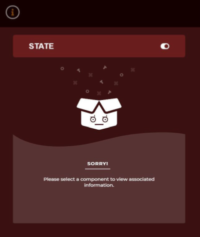
Figure 9. Details Pane Error Message
Figure 10. Information Display
Figure 11. Tech Manual Display | 1. Information displays general details and characteristics of the selected component. 2. Note: Press inside an information field to copy that name/data to use in Search. 3. State displays toggles for viewing or changing the operation, repair, or flow status of the selected component.
Figure 12. Details Pane Menu 4. Component Connections displays the relationships between components and identifies the connections as either incoming or outgoing. 5. Note: Press the magnifying glass icon to have Beast Core navigate the camera to the connection. 6. Tech Manuals show thumbnails of direct links to documents and diagrams that are associated with the selected component. |
Figure 13. State Display
Figure 14. Connections Display |
Avatar Viewer
Selecting Avatar Viewer
To access the Avatar Viewer, access the sidebar menu by selecting the Rotate icon.

Figure 15. 3D Rotate Icon
Next, select the Avatar option from the sidebar menu.
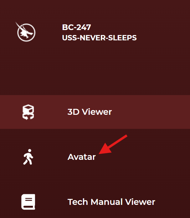
Figure 16. Avatar Option in Sidebar Menu
The Search screen opens with a default of the bridge on board the USS Never Sleeps. Select this option unless you prefer to navigate to another location onboard your vessel of choice.
.png)
Figure 17. Search Page with Bridge Selected as Default for Avatar to Start
Avatar Navigation
Using the bridge default as the starting point, you will see a compass in the lower left corner of the screen that shows the avatar orientation onboard the vessel. The navigation keyboard commands (Figure 5). They are:
• W = Forward
• S = Backward
• A = Sideways Left
• D = Sideways Right
.png)
Figure 18. Bridge of the USS Never Sleeps
Note: The following actions are using a PC. Mobile and Apple hardware may differ.
To begin, practice walking on the bridge.
When approaching a door colored RED, place the reticle on the door and left or right select the door.
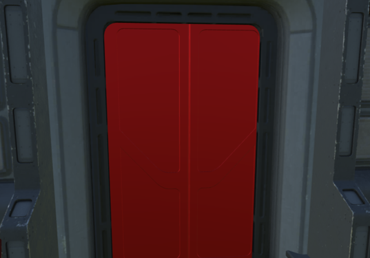
Figure 19. Door Closed or Not Accessible
If the door turns TEAL and then GREEN (Figure 19) when selected, you can move through the doorway.
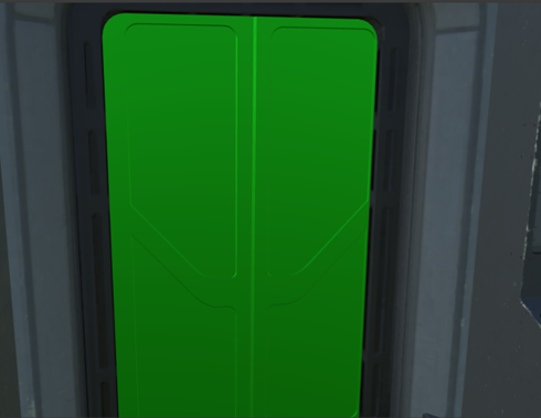
Figure 20. Door Open/Accessible
If the door remains RED after selection, you cannot move through that door.
As you approach the door and move through it, the next room or corridor opens before you.
.png)
Figure 21. From Bridge to Rack Room 1
On the left wall of Rack Room 1 is Ship Control System Data Processing Unit 3 (SCS-DP-3). Select the panel by tapping the left mouse while the reticle is hovering on the panel. This accesses the Information, Connections, and Tech Manual screens in Figure 22.
Panels and Diagram
.png)
.png)
.png)
Figures 22-24. Information, Connections, and Tech Manual Panels
Avatar Viewer has an option to navigate between components of a system. For this example, select the Ship Control System One Line Diagram (on left side of the Tech Manuals panel). See the GREEN rectangle in Figure 23. Each component is highlighted and has a link embedded into the document. When selecting a component, select the Avatar Viewer option (Figure 24), and a transit path appears. Following this helps the user navigate from one component to another.
(1).png)
Figure 25. Ship Control System One Line Diagram
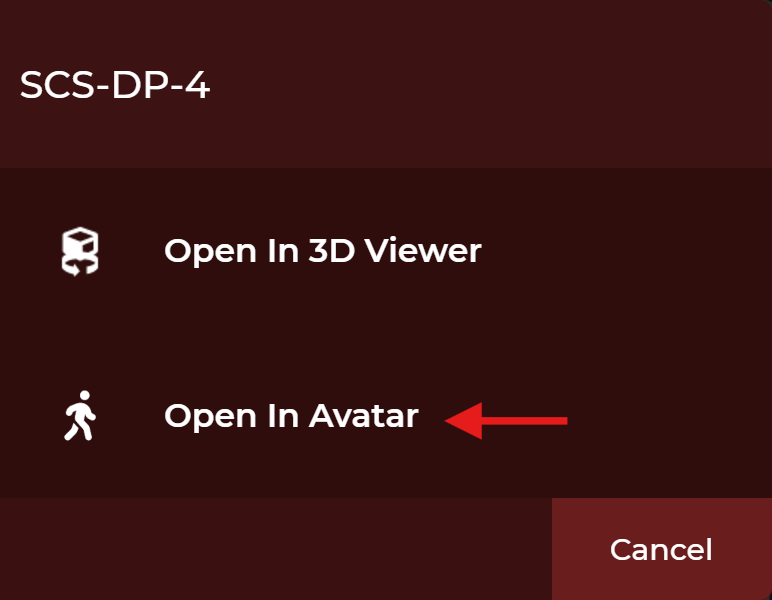
Figure 26. Select Avatar Viewer
Transit Path
The transit path appears as a blue line to guide the user to SCS-DP-15 in Pump Room 1.
.png)
Figure 27. Transit Path
.png)
Figure 28. SCS-DP-15 in Pump Room 1
Viewer Tools
The Viewer Tools menu has five tool options, Alignment, Platform, Visualizer, Search, and Controls. The guide has a section for each of these tools with a description and examples of each of them.
(2).png)
Figure 29. Viewer Tools Menu
Alignment
In Beast Core 4.10 Normal Operation is the only Alignment Option.
(3).png)
Figure 30. Alignment Option
Platform
When selected, this tool opens the Platform Options menu and allows the user to modify the Platform, Hull, and Systems options. This shows which Platform and Systems are currently selected and allows the user to adjust any of the options they choose. The user may cancel the menu or change the options and select Load which will change the presentation that includes the changes made.
(2).png)
Figure 31. Platform Options Menu
Visualizer
The Visualizer Tool has two options, described, and displayed below: System Designation and Static Flow.
System Designation
System Designation displays all the systems in the appropriate color schemes represented in the Platform Options Menu (Figure 29).
(1).png)
Figure 32. System Designation Tool
.png)
Figure 33. Systems Designated by the Platform Options Menu Color Schemes
Static Flow
Static Flow is a functional representation of the system(s), and each color represents a state (flow, no flow, missing support services). The components are colored based on flow:
• Dark Blue - open and connected to flow.
• White - not connected to flow.
• Yellow - component closed and interrupting flow.
• Red - component is damaged and interrupting flow.
• Teal - primary flow provided, but no flow from a dependency system.
(2).png)
Figure 34. Static Flow Tool
(1).png)
Figure 35. Static Flow Tool Display - Open and Connected to Flow
Search
The Search tool opens the search screen which has two areas, Select the platform you want to search within and then Search for a component or space. In the example below selecting the platform USS-NEVER-SLEEPS-LOD-SYSTEMS and entering the component PUMP into search for. The display shows first two rows of results.
(1).png)
Figure 36. Search Tool Search Results
Controls
A description of the three Controls and their behaviors are below:
• Viewer Speed – The default value of 50 is set. Sliding the control to the left will slow the speed. Sliding the control to the left increases the speed.
• Transparency – The default value of 40 is set. Sliding the control to the left makes the hull more transparent. Sliding the control to the right increases the opacity of the hull.
• Camera Snap-To – Selecting one of the orientations immediately moves the camera to that orientation to the hull.
Figure 37. Viewer Speed and Transparency Controls |
Figure 38. Viewer Camera Snap-To Controls |
.png)
.png)
.png)
.png)
.png)
(1).png)
.png)